Naval Armor and Ballistics (2.0)
This program is a melding of the ballistics logic from Robert McCoy’s MCTRAJ program and that from Nathan Okun’s armor penetration programs FACEHARD7.8 and NCWCLCR4. Naval Armor and Ballistics (NAaB) is written for MS-Windows in Borland’s Delphi.
To install the program unzip the contents into its own folder. The contents should be: NavalArmorBallistics.exe, DRAGFACT.dat, NAAB.lng, ProgInfo.txt, ProjNation.txt, ProjSelections.txt, file_id file and this PDF.
The NAaB should run in Windows by clicking on it.
The NAaB has two general areas of operation. The first one allows the user to compare a projectile against either face hardened armor plate or to homogeneous armor. The second area determines the ballistics of the projectile and then translates the trajectories striking angle and velocity to an impact on both types of armor at once.
1. The Face Hard Armor page. Select an armor type off the window list by clicking on a line. The armor can be made inclined for use with Ballistics computations but is not used in computations in the Vertical Impact page. Enter an armor thickness value. If the armor is highly curved or dome shaped check the check box. Press Ok when done entering. A column of entry boxes appears. This allows the entry in inches of the thickness of any backings of wood, concrete, or metal. If metal backing one to seven layers of specific type metal is allowed. If there is no backing just click the top radio button stating that and go to the next page.
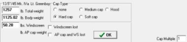
2. The Deck Armor page. Select an armor type off the list by clicking on a line in the window. Besides deck armor various types of non-cemented armor are listed which may be used for vertical armor. Enter a armor thickness value. The BHN entry box allows the user to change the quality based on the Brinell Hardness Number (BHN). When doing this set the quality to 1.0. The program will adjust the working quality to a multiple based on US Army M62 vs. armor hardness effective ness tests. When the BHN is set to 235 the program uses the quality value for working quality. Don’t change both. When done entering press the OK button.
Note - When entering or changing data the ‘OK’ buttons are not activated until some data is entered or changed.
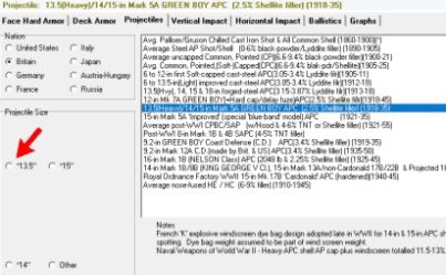
3. The Projectiles page. Click on a nation. The window on the right will show an number of gun/projectile classes to select from. Click on a line of projectile class. A set of radio buttons labeled with projectile sizes will appear at the lower left. An * will appear to the left of the size indicates there is data already in the Projlist file for the selection. If there are more than one gun/shell in the data when it is selected a list of up to 7 candidates will appear. Select one of them by clicking on the row. In any case when a shell is selected a number of boxes will appear below the projectile class window. The boxes will load data from a matching entry in the projectile file. This is a suggested weight, but it may not be the projectile weight that you want. You can change these values. Both total weight and body weight are required.
A windscreen weight can also be added. Any difference of the sum of the windscreen and body weight from the total weight will automatically be put into the armor piercing cap/hood weight. For the most point the cap cannot be changed as it is determined by the shell class. The exception is that the hard cap can be changed from the standard cap as on the ‘hard’ cap 6-in Mk. 35 mod projectile to one like on the ‘medium’ cap 76mm M62 APCBC-HE tank gun projectile.
The optional Cap Multiple entry box in the lower right corner lowers or raises the overall penetration values based on a cap multiple factor. (Note this is 1/(cap multiple) found in HCWCLCR.) It’s effect is that it lowers or raises the penetration of all capped projectiles.
Press OK to use your choices for ballistic testing.
At this point you can go to one of the Impact pages or the Ballistics page. They are independent functions.
4. Vertical Impact page. This is Facehard armor. Enter a velocity of the projectile impact. Enter a specific angle of impact. Note that the armor incline is ignored here. Press OK. To the right you will see the detailed penetration effects of the projectile impact. Below the button is listed the values of the different levels of penetration.
5. Horizontal Impact page. Enter a velocity of the projectile impact. Enter a specific angle of impact. Press OK. To the right you will see the detailed penetration effects of the projectile impact. Below the button is listed the values of the different levels of penetration.
6. The Ballistics page. This is intended to show the effects of the projectile over its trajectory range. Enter the Muzzle Velocity and Ballistic Coefficient. With certain projectiles a suggested velocity and coefficient are entered for the user. The user may change this if he desires. There also is a selection for a number of Gâvre drag functions.
An advanced function is the Drag Coefficient which is the alters the ballistic coefficient. In WWII it was found that the Gâvre functions didn’t quite describe the ballistic characteristics of a projectile. Several other factors were added to the ballistic equations. In this variable I just combine those factors into a single additional factor, the Drag Coefficient. A positive number here slightly increases the ballistic coefficient with the range increase while a negative number slightly decreases it.
The Range Intervals option selects the range intervals that the program will report the penetration, range, striking velocity and angle of descent. A radio group selection of range increments can be selected. Users may select Yards or Meters for output. Also either Face Hard or Homogeneous armor types can be selected. Both vertical or horizontal aspects can be selected.
The user may change yards for meters by clicking on the button that reads Yards or Meters.
The ‘Deck’ levels are for the selected armor when at the horizontal. To view face hard armor or rolled homogenous armor switch the armor types.
The levels of penetration can be selected. Full US Naval Ballistic Limit (NBL) perforation and Proof limits can selected. Also for vertical armor a partial penetration level can be seen. This is in the realm of Army Ballistic Limit (ABL). For HE (High Explosive) shell the definition is different. Perforation value would be destruction or shattering of the armor thickness. No penetration level of HE is the value that minimal deformation of armor occurs.
The Override button allows the user to input a new maximum range or a starting elevation. The maximum elevation is for reference only.
Tools: There are two tool buttons at the bottom of the page.
A. Fire Salvo Tool. (Requires Muzzle Velocity and Ballistic Coefficient) This fires projectile at the selected elevation which results in the range the projectile attains.
B. Find B.C. Tool. (Requires Muzzle Velocity with optional Drag Coefficient change) This is a multi-function tool.
B1. If the Set Range is entered with 0 in Set Strike field then the program will use the value in the Elevation field to find the ballistic coefficient in terms of the G1 drag function.
B2. If both the Set Range and Set Strike fields are filled the ballistic coefficient in terms of the
G1drag function will be found.
B3. If the Set Range, Set Strike, Opt Range, and Opt Strike fields are filled the best match with ballistic coefficients among all Gâvre drag functions will be found.
Input of ranges and strikes must be in Yards or Meters depending on Output Yards/Meters button.
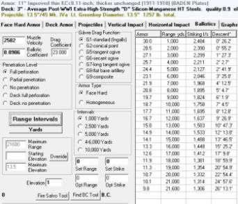
7. The Charts page. This is mostly self-explanatory as it lets the user see the plot of the Ballistic data.
8. Various Files.
A. The Naab.lng file. This is most of the long text messages used by the program. It is left outside the program in case anyone wants to translate it to another language.
The following three files have data lines that are linked by designation projectile size key.
B. ProjInfo.txt. This is an editable file the data from where projectile ballistic data is read into the program. Each line will represent a specific gun and shell. Each line starts with a text gun name delimited by a ‘#’ After that a series of numbers are listed. These have a specific format so read the explanation in the first section of the file.
C. ProjNation.txt. This is an editable file that controls which designation projectile sizes are used in projectile selection by nation. The data line includes nation, designation projectile size, and actual size.
D. ProjSelection.txt. This is an editable file that controls the display of designation projectile sizes that can be selected when a projectile line is clicked.
E. DRAGFACT.dat are data files and should not be altered.
Notes
1. The ballistic tools are meant to locate the best ballistic coefficient. My reason for this is to have the correct striking velocity at the specified ranges. This is important for armor penetration calculations. I use the B.C. finding tool to find the best match to the actual firing table numbers.
There is sometimes no correct setting but best compromise. The Drag Coefficient is a scaled by range correction (when velocity is above the speed of sound) of the Ballistic Coefficient. (While this should more properly be a function of air pressure from velocity it is not linear so after a complicated formula a ratio to range has acceptable results.)
2. HE penetration uses in part an equation found on Nathan Okun’s website. I modified it to take into account shell weight rather than diameter size. I don’t have HE armor penetration tables. I do have Aberdeen derived armor deformation tables of HEshell detonations and I have TM 9 1907 tables of HE shell ballistics pertaining in concrete penetration. (Some US Army gun/projectiles included in the pre-loaded gun list were used for testing.) The conversion from concrete to armor penetration has some varying of opinion. I’ve gone with 12.5 : 1 of concrete to armor penetration while some sources have it at 10 :1. (Others range from 6 :1 to 25 : 1.) On the NavWar site (http://navweaps.com/Weapons/WNUS_16-50_mk7.php) USN 16" concrete to armor penetration ratio ranges from 12.2-12.6 : 1.
3. Penetration of homogeneous armor is reduced by the use of the Plim and Pdam shell quality factors found in the Face Hard program. A weighed average ‘(3*Plim/4 + Pdam/4)^0.75' is divided into the NBL limit thus reducing the penetration of the low quality shells.
4. Some Ground combat guns/shells have been added to the usual mix of naval shells.
Definition of NBL
The Navy Ballistic Limit criterion demands that at least half the weight of the projectile pass through the plate. “A complete penetration occurs when the entire projectile or the major portion of the projectile passes completely through the armor.” (www.dtic.mil/dtic/tr/fulltext/u2/310022.pdf)
(The ‘major portion” being at least half the mass.) Note – this results in the criteria (V50) being a 50% chance of 50+% of the mass passing through the armor.
The Army Ballistic Limit criterion requires only that light shall show through the hole in the plate when the shot is removed, i.e. a partial penetration.
Specifications: g: 9.80665m/sec. Elevation: sea level. Atmospheric pressure ratio: 1.0. Standard temperature 59̊/F
Facehard 7.8 and Hcwclcr4 programs by Nathan Okun.
(http://www.panzer-war.com/ )
NAaB 2.0 program by Steven Lorenz Copyright 2018.